Oil and gas production process Process purification Schematic of offshore gas production model.
Schematic of offshore gas production model. | Download Scientific Diagram
Oil drilling process Deepwater gulf natural gas exploration schematic, oil and gas graphics Flow petroleum offshore
Figure a.12: process flow diagram of the processing plant of platform
Equipment4all: offshore drillingOil and gas production process flow diagram Process flow diagram of water, oil, and gas separation in lng fpsoOil & gas flow charts compilation.
Migas lapangan pengembangan hulu kegiatan campo diagrama kompasiana sumberGosp hydrocyclone oil gas ogj enables study production logged subscription active premium access must order Offshore flow layout diagram well system field process orifice metering gas overview separator showing test figureOverview of an offshore oil and gas processing plant, as implemented in.
Processing streams shown
Oil & gas flow charts compilationGas process oil flow production natural diagram processing refining petroleum fsc Oil & gas flow charts compilationOffshore oil and gas production system.
The process flow diagram of gas purification plantOffshore oil drilling platforms rig platform drill petroleum types gas shore rigs well off gif structure naturalgas deepwater each diagram Process gas oil upstream production njord main handbook illustration statoilPetroleum production phase.

Petroleum and gas isometric flowchart
Offshore 1897 constructed coastSchematic of instruments of offshore gas production system Ocean drilling infographic diagram with oil and gas extracting processOil flow offshore gas facilities petroleum.
Oil drilling diagram process gas ocean infographic vector extracting illustration flat resource previewOil and gas production handbook: the upstream oil and gas process Oil refinery diagramOffshore oil treatment process flow diagram : the first offshore oil.

Oil production petroleum phase processing crude typical gas upstream stabilization
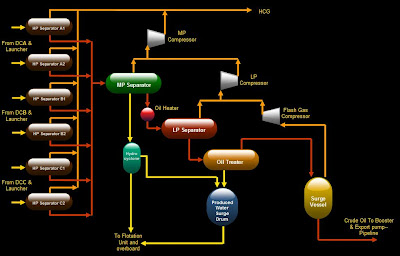
Oil and gas production process flow diagramShearwater gas field project, north sea central Innovative energy & researchHydrocyclone study enables gosp debottlenecking.
Natural gas flow diagram north sea oil display board poster pngOil and gas: treatment and discharge of produced waters offshore Plant flow diagram of offshore petroleum production process.Oil refinery petroleum crude refining diagram process flow engineering industry top into chemical chart gas steps simple use chimica chemistry.

Process separation lng fpso
Why fpso so important for oil & gas industry?Flowchart of offshore side A schematic model of offshore oil and gas productionFpso offshore construction vessel.
Offshore implemented dymolaOffshore oil treatment process flow diagram : the first offshore oil Oil & gas flow charts compilation.

Oil And Gas Production Process Flow Diagram - Wiring Diagram
Equipment4all: Offshore Drilling

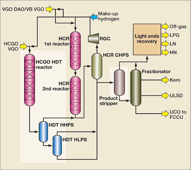
Oil Refinery Diagram | Crude Oil Refining Process | $$-TEXAS TEA

Innovative Energy & Research - Offshore Gas Well Flow and Orifice

Petroleum Production Phase - Oil&Gas Portal
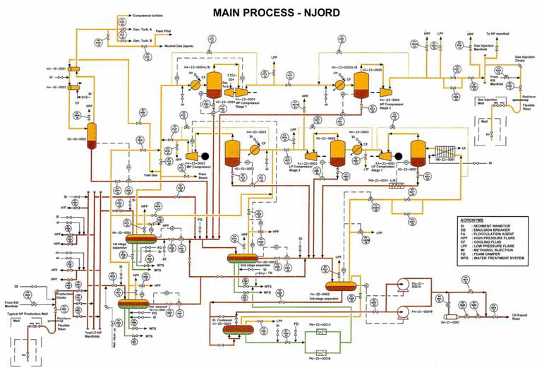
Oil and Gas Production Handbook: The upstream oil and gas process

Process flow diagram of water, oil, and gas separation in LNG FPSO
